Manufacturing Instructions
Overview
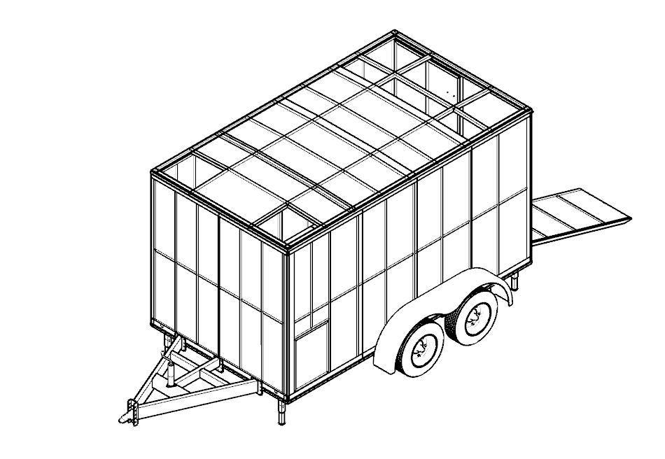
The step-by-step manufacturing and assembly process for a Bolt-on Box Trailer. It incorporates boltable side walls, roof, A-frame, and all other components, allowing for easy and efficient transportation and reassembly of the trailer.
Material Preparation
- Cut all frame sections, plates, and tub panels according to the engineering drawings (provided in 2d drawing section).
- Deburr all components and clearly label them for easy identification during assembly (use part numbers noted in the relevant drawing).
- Prepare all sub-assemblies based on drawings referring the all instructions noted.
- Ensure all parts are laser-cut or CNC-cut where applicable, for maximum accuracy.
- Bolt holes are very important and location of the bolt holes should be high precision.
- Use general tolerance as +/- 1mm.
Chassis Frame Fabrication
- Frame Structure:
- Follow the cross-member assembly drawings to prepare the main structure of the trailer.
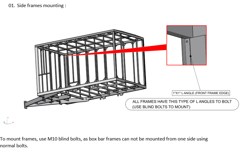
- Follow the side wall assemblies, rear wall assembly, rear doors and front A frame assembly drawings to prepare those sub-assemblies.
- Maintain proper inspection for all welding and hole location details for assembling.
- Align main beams, cross members, and ensure squareness using jigs and fixtures (If you want more details of the jigs and fixtures contact us). This will help to reduce the assembling issues after complete the separate sub-assemblies such as side walls and A frame.
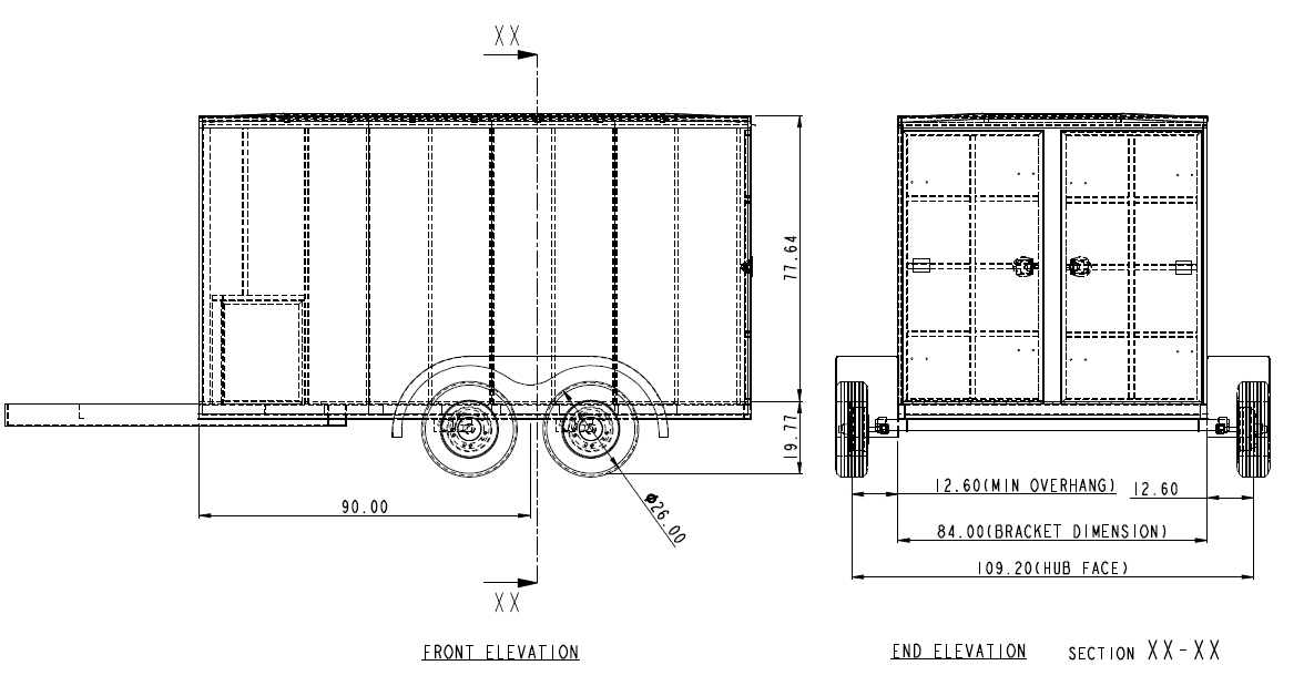
- Leave clearance space in front and behind the axle for balanced weight distribution and potential component additions.
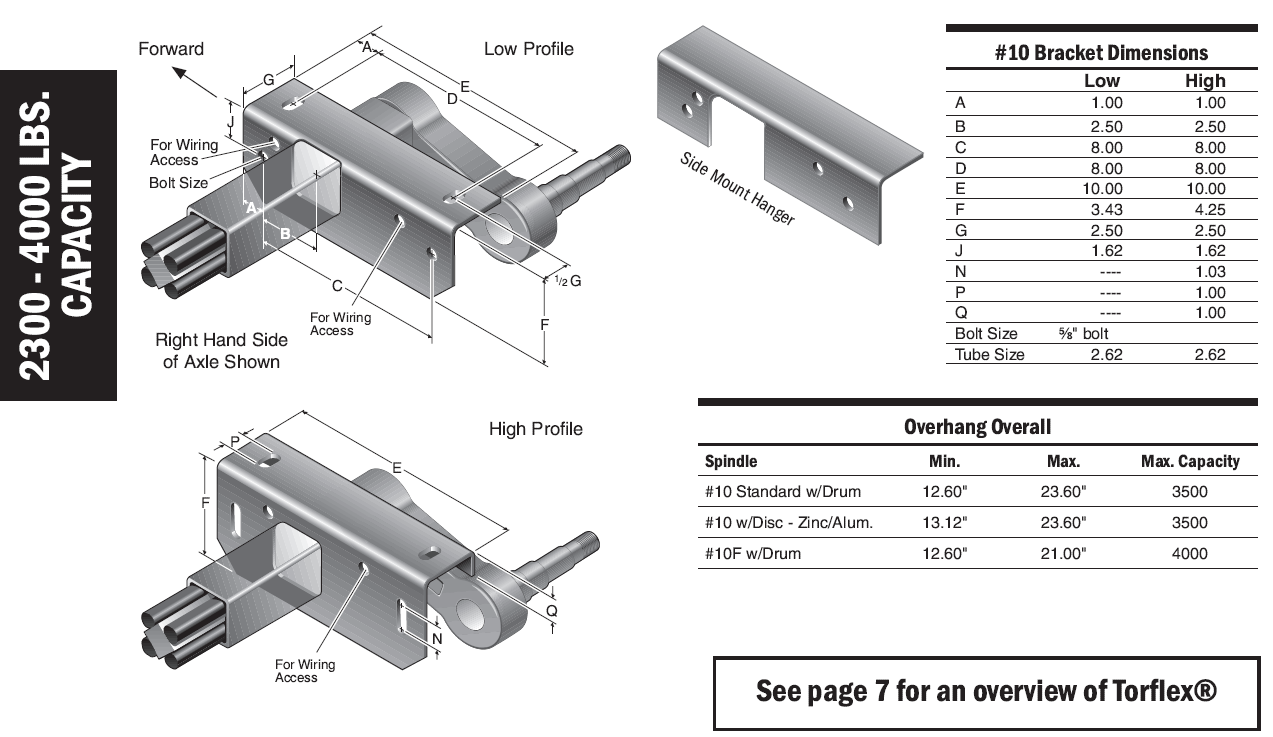
- Bolt suspension brackets and axle mounts accurately.
- Integrate a rear hitch mount capable of towing a bicycle carrier or similar load.
Sub-Assembly Components
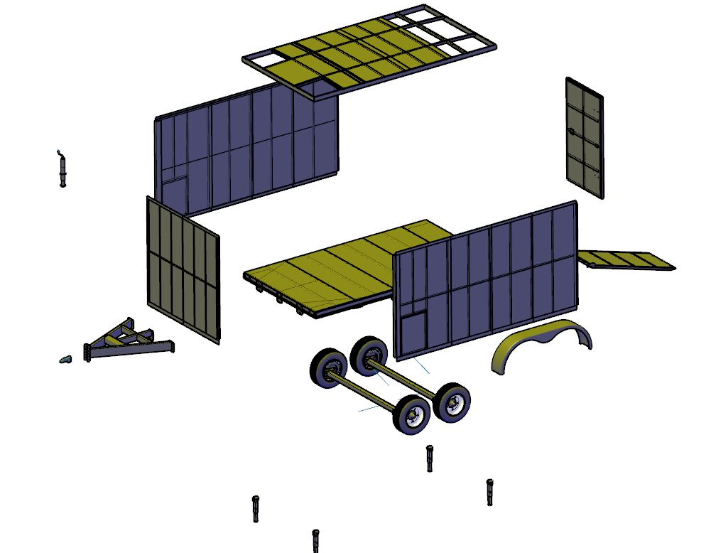
- Pre-assemble sub-components off the main frame:
- Side Walls
- Rear Wall
- Rear and Side Doors
- Mud Guards
- A Frame Assembly
- Electrical system
- Tie-down points
- Hitch receiver
Wall ad Chassis Fabrication and Assemble
- Fabricate all parts of the top bucket and construct the bucket referring the relevant drawings and securely fastened to the frame.
- Add bolt-on fenders correctly and tighten them.
- Bolt suspension brackets and axle mounts accurately.
- Use relevant assembly drawing to mark the correct location for Towing hitch, landing legs and front adjustable landing leg.
- Do the axle alignments after finish the cross assembly and A frame assembly assembled together.
- Floor plates, side wall inner and outer plates should be mounted after finish the trailer frame assembled correctly.
Fabrication tools and techniques
- Utilize a hydraulic folder whenever possible for forming operations to ensure consistency and precision.
- Ensure all fabricated parts are suitable for laser cutting or CNC processing for ease of reproduction and quality assurance.
Surface preparation and finishing
- Perform shot blasting to clean the aluminum surfaces.
- Apply suitable primer and finish with either powder coating or industrial epoxy paint depending on application requirements (Contact for more details).
Final assembly instructions
Stage 1: Chassis Setup
- Position the finished chassis on supports in the assembly bay.
Stage 2: Suspension and Axle
- The Axle-less suspension provides many advantages and permits many innovative designs for trailers. There is no thru axle and therefore the two sides of suspension are completely independent.
- Axle-less suspensions are not recommended for tri-axle applications. Even loading is important (Since there is no equalization between axles).
- Install outboard arm on control arm using 4 bolts and washers and shims as required (verify that bolts are grade 8.0). The left-hand side is the mirror image.
- Make sure frame is perfectly square. Measure and compare the diagonal distance from one corner of frame to the opposite corner. Also measure and compare the distances from the hitch to each rear corner of frame.
- Mark frame rails where centerline of spindle (wheels) should cross frame.
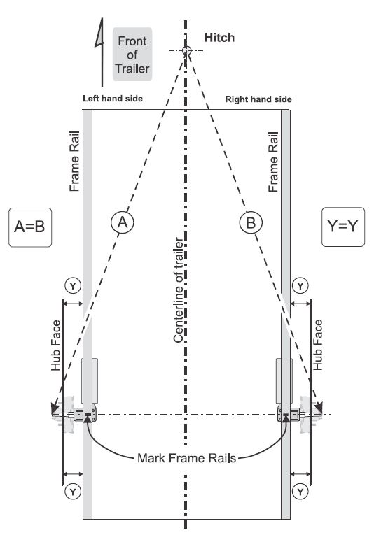
- Locate the left hand and right hand side hangers on frame rails, opposite to each other. Move hangers along frame until center of spindles line up with marks on the frame rails, viewing from top. Clamp hangers to frame. Measure and compare distances “A” and “B”. Reposition hangers until the difference between “A” and “B” measurements is less than 1/8’’ (3mm).
- Be aware that the suspension has camber angles built in. The correct alignment can be obtained only if frame and its crossmembers or mounting surfaces to the suspension are perfectly square and they are sufficiently strong to remain square under maximum loads.
Stage 3: Accessory Installation
- Attach jack stand, coupler, stabilizers, and tie-down loops.
- Install Rear Door and Side doors.
- Exterior wall finish – Polycor /AP
- Interior wall – Painted 0.5’’ plywood (Possible alternative is Polycor /AP)
- Interior Floor 0.75’’ plywood with coin rubber floor
- Add standard Aluminum top rail
- Add standard Aluminum bottom rail
- Aluminum drip edge over all three openings
- Luan ceiling liner strips
- Metal door holdback on all three doors
- Red and Yellow reflective tapes for markings
Stage 4: Floor and Tub Panels
- Secure floor plate and side/tub panels to the frame using bolts or structural welds.
Stage 5: Electrical Wiring
- Route cables through installed clips.
- Connect lighting systems (tail lamps, side markers) and verify proper grounding.
Stage 6: Wheels and Tires
- Install wheels and torque lug nuts to specified torque values – 90-95 ft-lbs (122 – 129 Nm).
Stage 7: Final Checks and Testing
- Conduct a visual inspection of welds and fasteners.
- Check overall dimensional accuracy and alignment.
- Perform a functional test on tailgate, hitch, suspension, and electrical systems.
- Conduct a static load test if applicable, to validate structural integrity.
Stage 7: Notes and Recommendations
- All fabrication and assembly should comply with local roadworthiness regulations and trailer manufacturing standards.
- Maintain detailed logs of component inspections, welding certifications (if any), and test results for future reference or certification.
Content
Mouse over or long press for description.